FaceSwap
Table of Contents:
- 1. Deadline
- 2. Introduction
- 3. Data Collection
- 4. Phase 1: Traditional Approach
- 5. Phase 2: Deep Learning Approach
- 6. Notes about Test Set
- 7. Submission Guidelines
- 8. Debugging Tips
- 9. Allowed and Disallowed functions
- 10. Collaboration Policy
- 11. Acknowledgements
1. Deadline
11:59PM, March 17, 2024.
2. Introduction
The aim of this project is to implement an end-to-end pipeline to swap faces in a video just like Snapchat’s face swap filter or this face swap website. It’s a fairly complicated procedure and variants of the approach you’ll implement have been used in many movies.
One of the most popular example of using such a method is replacing Paul Walker’s brother’s face by Paul Walker’s face in the Fast and Furious 7 movie after his sudden death in a car crash during shooting. Now that I have conviced you that this is not just for fun but is useful too. In the next few sections, let us see how this can be done.
Note that, you’ll need to be aware of ethical issues while replacing faces. Similar methods are used by people for the creation of fake videos of celibrities called Deep Fakes.
3. Data Collection
Record two videos. One of yourself with just your face and the other with
your face and your friend’s face in all the frames. Convert them to .avi or .mp4 format.
Save them to the Data folder. Feel free to play around with more videos. In the first video,
we’ll replace your face with some celebrity’s face or your favorite relative’s face. In the
second video we’ll swap the two faces. If there are more than two faces in the video, swap
the two largest faces.
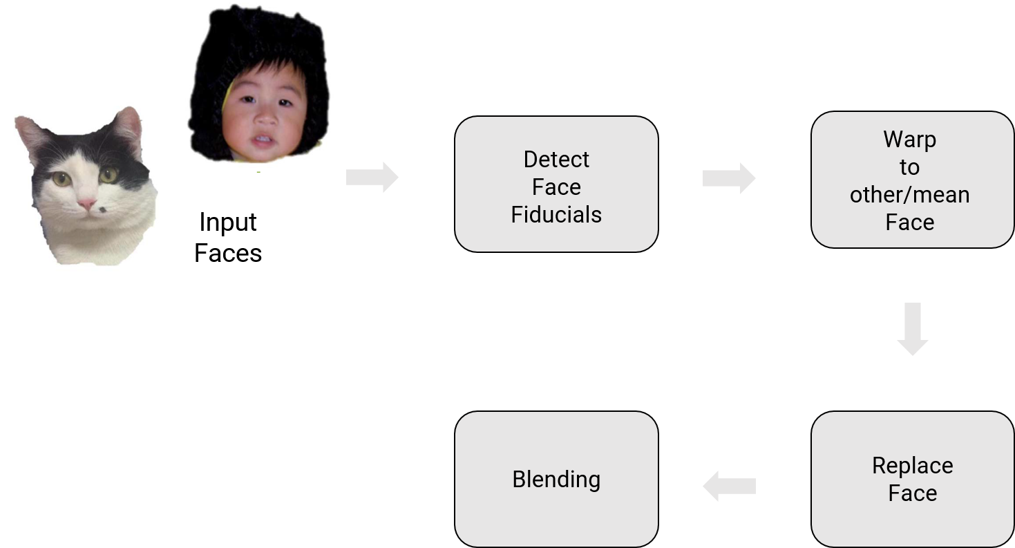
4. Phase 1: Traditional Approach
The overview of the system for face replacement is shown below.
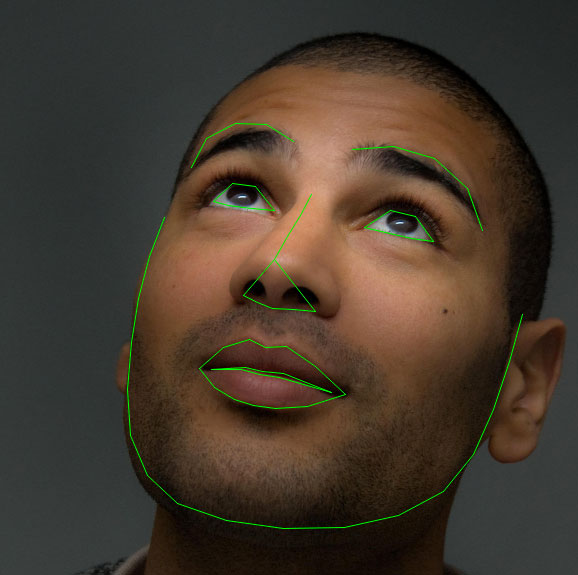
4.1. Facial Landmarks detection
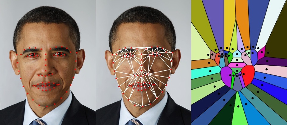
The first step in the traditional approach is to find facial landmarks (important points on the face) so that we have one-to-one correspondence between the facial landmakrs. This is analogous to the detection of corners in the panorama project. One of the major reasons to use facial landmarks instead of using all the points on the face is to reduce computational complexity. Remember that better results can be obtained using all the points (dense flow) or using a meshgrid. For detecting facial landmarks we’ll use dlib library built into OpenCV and python. A sample output of Dlib is shown below.
4.2. Face Warping using Triangulation
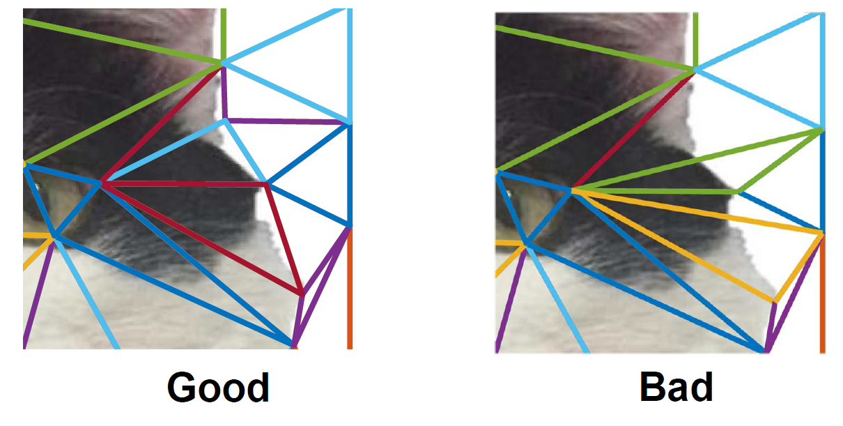
Like we discussed before, we have now obtained facial landmarks, but what do we do with them? We need to ideally warp the faces in 3D, however we don’t have 3D information. Hence can we make some assumption about the 2D image to approximate 3D information of the face. One simple way is to triangulate using the facial landmarks as corners and then make the assumption that in each triangle the content is planar (forms a plane in 3D) and hence the warping between the the triangles in two images is affine. Triangulating or forming a triangular mesh over the 2D image is simple but we want to trinagulate such that it’s fast and has an “efficient” triangulation. One such method is obtained by drawing the dual of the Voronoi diagram, i.e., connecting each two neighboring sites in the Voronoi diagram. This is called the Delaunay Triangulation and can be constructed in \(\mathcal{O}(n\log{}n)\) time. We want the triangulation to be consistent with the image boundary such that texture regions won’t fade into the background while warping. Delaunay Triangulation tries the maximize the smallest angle in each triangle.
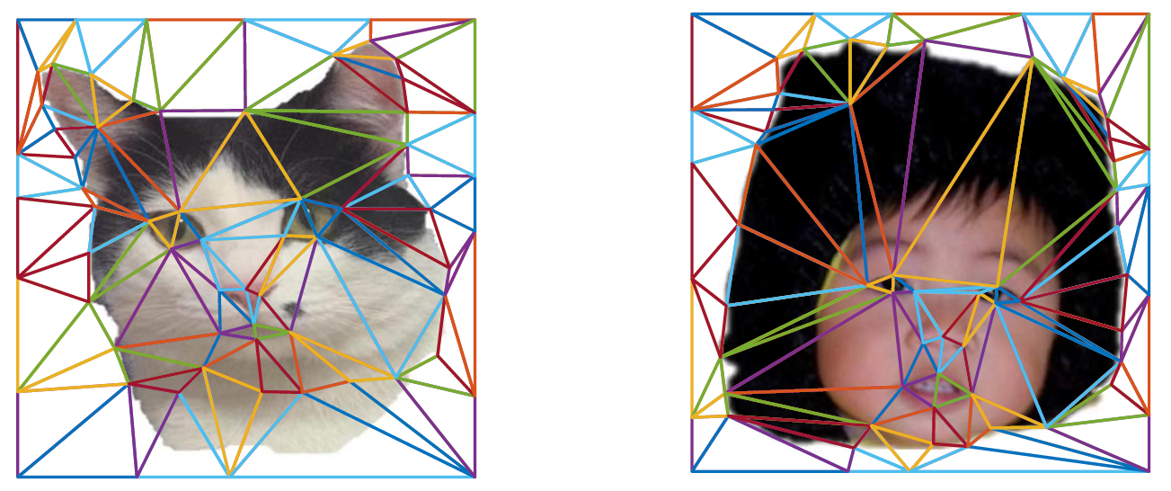
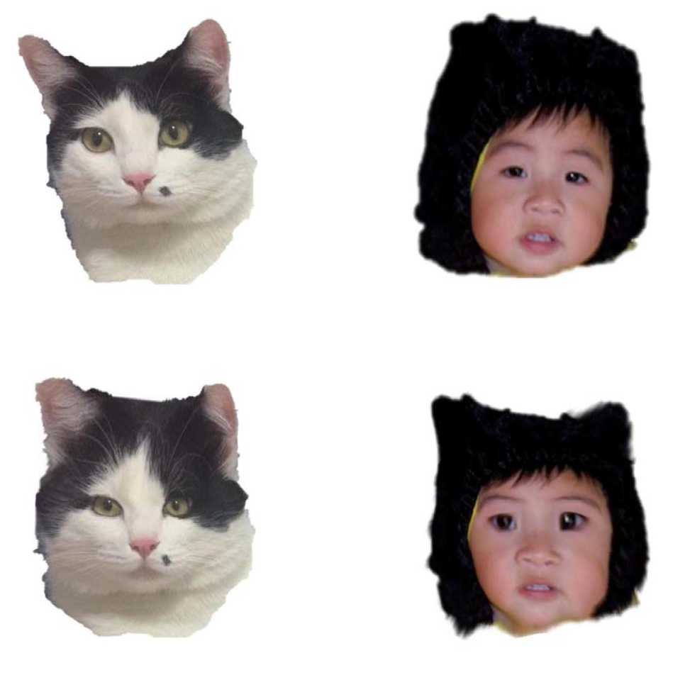
Since, Delaunay Triangulation tries the maximize the smallest angle in each triangle, we will obtain the same triangulation in both the images, i.e., cat and baby’s face. Hence, if we have correspondences between the facial landmarks we also have correspondences between the triangles (this is awesome! and makes life simple). Because we are using dlib to obtain the facial landmarks (or click points manually if you want to warp a cat to a kid), we have correspondences between facial landmarks and hence correspondences between the triangles, i.e., we have the same mesh in both images. Use the getTriangleList() function in cv2.Subdiv2D class of OpenCV to implement Delaunay Triangulation. Refer to this tutorial for an easy start. Now, we need to warp the destination face to the source face (we are using inverse warping so that we don’t have any holes in the image, read up why inverse warping is better than forward warping) or to a mean face (obtained by averaging the triangulations (corners of triangles) of two faces). Implement the following steps to warp one face (\(\mathcal{A}\) or source) to another (\(\mathcal{B}\) or destination).
- Step 1: For each triangle in the target/destination face \(\mathcal{B}\), compute the Barycentric coordinate.
Here, the Barycentric coordinate is given by \(\begin{bmatrix} \alpha & \beta & \gamma \end{bmatrix}^T\). Note that, the matrix on the left hand size and it’s inverse need to be computed only once per triangle. In this matrix, \(a, b, c\) represent the corners of the triangle and \(x,y\) represent the \(x\) and \(y\) coordinates of the particular triangle corner respectively.
Now, given the values of the matrix on the left hand size we will call \(\mathcal{B}_{\Delta}\) and the value of \(\begin{bmatrix} x & y & 1 \end{bmatrix}^T\) we can compute the value of \(\begin{bmatrix} \alpha & \beta & \gamma \end{bmatrix}^T\) as follows:
\(\begin{bmatrix} \alpha \\ \beta \\ \gamma \\ \end{bmatrix} = \mathcal{B}_{\Delta}^{-1} \begin{bmatrix} x \\ y \\ 1\\ \end{bmatrix}\) Now, given the values of \(\alpha, \beta, \gamma\) we can say that a point \(x\) lies inside the triangle if \(\alpha \in [0, 1]\), \(\beta \in [0, 1]\), \gamma \in [0, 1] \(and\)\alpha + \beta + \gamma \in (0,1]$$. DO NOT USE any built-in function for this part.
- Step 2: Compute the corresponding pixel position in the source image \(\mathcal{A}\) using the barycentric equation shown in the last step but with a different triangle coordinates. This is computed as follows:
Here, \(\mathcal{A}_{\Delta}\) is given as follows:
\[\mathcal{A}_{\Delta} = \begin{bmatrix} \mathcal{A}_{a,x} & \mathcal{A}_{b,x} & \mathcal{A}_{c,x}\\ \mathcal{A}_{a,y} & \mathcal{A}_{b,y} & \mathcal{A}_{c,y}\\ 1 & 1 & 1\\ \end{bmatrix}\]Note that, after we obtain \(\begin{bmatrix} x_{\mathcal{A}} & y_{\mathcal{A}} & z_{\mathcal{A}} \end{bmatrix}^T\), we need to convert the values to homogeneous coordinates as follows:
\[x_{\mathcal{A}} = \frac{x_{\mathcal{A}}}{z_{\mathcal{A}}} \text{ and } y_{\mathcal{A}} = \frac{y_{\mathcal{A}}}{z_{\mathcal{A}}}\]- Step 3: Now, copy back the value of the pixel at \((x_{\mathcal{A}}, y_{\mathcal{A}} )\) to the target location. Use
scipy.interpolate.interp2dto perform this operation.
The warped images are shown below.
4.3. Face Warping using Thin Plate Spline
As we discussed before, triangulation assumes that we are doing affine transformation on each triangle. This might not be the best way to do warping since the human face has a very complex and smooth shape. A better way to do the transformation is by using Thin Plate Splines (TPS) which can model arbitrarily complex shapes. Now, we want to compute a TPS that maps from the feature points in \(\mathcal{B}\) to the corresponding feature points in \(\mathcal{A}\) . Note that we need two splines, one for the \(x\) coordinate and one for the \(y\). Imagine a TPS to mathematically model beating a metal plate with a hammer. A thin plate spline has the following form:
\[f(x,y) = a_1 + (a_x)x + (a_y)y + \sum_{i=1}^p{w_i U\left( \vert \vert (x_i,y_i) - (x,y)\vert \vert_1\right)}\]Here, \(U(r) = r^2\log (r^2 )\).
Note that, again in this case we are performing inverse warping, i.e., finding parameters of a Thin Plate Spline which will map from \(\mathcal{B}\) to \(\mathcal{A}\). Warping using a TPS is performed in two steps. Let’s look at the steps below.
- Step 1: In the first step, we will estimate the parameters of the TPS. The solution of the TPS model requires solving the following equation:
where \( K_{ij} = U\left( \vert \vert (x_i,y_i)-(x_j,y_j) \vert \vert_1 \right)\). \(v_i = f(x_i,y_i)\) and the ith row of \(P\) is \((x_i, y_i, 1)\). \(K\) is a matrix of size size \(p \times p\), and \(P\) is a matrix of size \(p \times 3\). In order to have a stable solution you need to compute the solution by:
\[\begin{bmatrix} w_1 \\ w_2 \\ \vdots \\ w_p \\ a_x \\ a_y \\ a_1 \end{bmatrix} = \left(\begin{bmatrix} K & P\\ P^T & 0\\ \end{bmatrix} + \lambda I(p+3, p+3)\right)^{-1} \begin{bmatrix} v_1 \\ v_2 \\ \vdots \\ v_p \\ 0 \\ 0 \\ 0 \end{bmatrix}\]where \(I(p+3,p+3)\) is a \(p+3 \times p+3\) identity matrix. \(\lambda \ge 0\) but is generally very close to zero. Think about why we need this. Note that you need to do this step twice, once for \(x\) co-ordinates and once for \(y\) co-ordinates.
- Step 2: In the second step, use the estimated parameters of the TPS models (both \(x\) and \(y\) directions), transform all pixels in image \(\mathcal{B}\) by the TPS model. Now, read back the pixel value from image \(\mathcal{A}\) directly. The position of the pixels in image \(\mathcal{A}\) is generated by the TPS equation (first equation in this section).
Note that, both warping methods solve the same problem but with different formulations, you are required to implement both and compare the results.
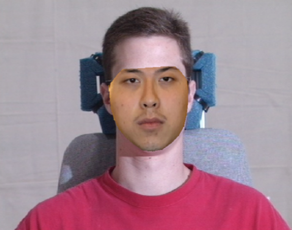
4.4. Replace Face
This part is very simple, you have to take all the pixels from face \(\mathcal{A}\), warp them to fit face \(\mathcal{B}\) and replace the pixels. Note that simply replacing pixels will not look natural as the lighing and edges look different. A sample output of face replacement is shown below.
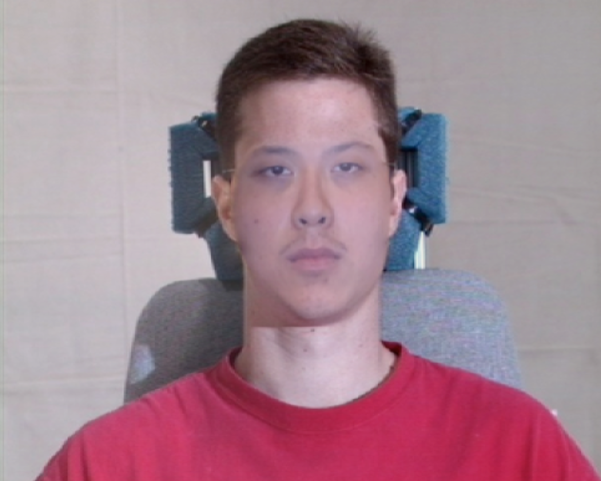
4.5. Blending
We will follow a method called Poisson Blending to blend the warped face onto the target face. More details about this method can be found in this paper. Note that, you DO NOT have to implement this part from scratch, feel free to use any open-source implementation and cite your source in your report and your code. Your task in this part is to blend the face as seamlessly as possible. Feel free to reuse concepts you learnt from panorama stitching project’s last part here. A good blending output is shown below.
4.6. Motion Filtering
After you have detected, warped and blended the face your algorithm works really well for individual frames. But when you want to do this for a video, you’ll see flickering. Come up with your own solution to reduce the amount of flickering. You can use a low-pass filter or a fancy Kalman Filter to do this. Feel free to use any third party or built-in code to do this. If you use third party code, please do not forget to cite them. Look at this holy grail video of face replacement where Jimmy Fallon interviews his cousin.
Jimmy Fallon interview his twin! from ZeroCool22 on Vimeo.
5. Phase 2: Deep Learning Approach
For this phase, we’ll run an off-the-shelf model to obtain face fiducials using deep learning. We think that implementing this part is fairly trivial and is left as a fun exercise if you want some programming practice (you are not graded for the implementation of the network). We’ll use the code from this paper, which implements a supervised encoder-decoder model to obtain the full 3D mesh of the face. We recommend you to read the paper for more details. The code from the paper can be found here. Your task is to setup the code and run to obtain face fiducials/full 3D mesh. Use this output to perform face replacement as before. Feel free to use as much code as you want from last part/phase. Present a detailed comparison of both the traditional methods (triangulation and TPS) along with the deep learning method.
6. Notes about Test Set
One day (24 hours) before the deadline, a test set will be released with details of what faces to replace. We’ll grade on the completion of the project and visually appealing results.
7. Submission Guidelines
If your submission does not comply with the following guidelines, you’ll be given ZERO credit
7.1. File tree and naming
Your submission on ELMS/Canvas must be a zip file, following the naming convention YourDirectoryID_p2.zip. If you email ID is abc@umd.edu or abc@terpmail.umd.edu, then your DirectoryID is abc. For our example, the submission file should be named abc_p1.zip. The file must have the following directory structure because we’ll be autograding assignments. The file to run for your project should be called Wrapper.py. You can have any helper functions in sub-folders as you wish, be sure to index them using relative paths and if you have command line arguments for your Wrapper codes, make sure to have default values too. Please provide detailed instructions on how to run your code in README.md file. Please DO NOT include data in your submission.
YourDirectoryID_p2.zip
│   README.md
|   Your Code files
|   ├── Any subfolders you want along with files
|   Wrapper.py
|   Data
|   ├── Data1.mp4
|   ├── Data2.mp4
|   ├── Data1OutputTri.mp4
|   ├── Data1OutputTPS.mp4
|   ├── Data1OutputPRNet.mp4
|   ├── Data2OutputTri.mp4
|   ├── Data2OutputTPS.mp4
|   ├── Data2OutputPRNet.mp4
└── Report.pdf
7.2. Report
For each section of the project, explain briefly what you did, and describe any interesting problems you encountered and/or solutions you implemented. You MUST include the following details in your writeup:
- Your report MUST be typeset in LaTeX in the IEEE Tran format provided to you in the
Draftfolder (Use the same draft folder from P1) and should of a conference quality paper. - Present the Data you collected in
Datafolder with namesData1.mp4andData2.mp4(Be sure to have the format as.mp4ONLY). - Present the output videos for Triangulation, TPS and PRNet as
Data1OutputTri.mp4,Data1OutputTPS.mp4andData1OutputPRNet.mp4for Data 1 respectively in theDatafolder. Also, present outputs videos for Triangulation, TPS and PRNet asData2OutputTri.mp4,Data2OutputTPS.mp4andData2OutputPRNet.mp4for Data 2 respectively in theDatafolder. (Be sure to have the format as.mp4ONLY). - For Phase 1, present input and output images for two frames from each of the videos using both Triangulation and TPS approach.
- For Phase 2, present input and output images for two frames from each of the videos using PRNet approach.
- Present failure cases for both Phase 1 and 2 and present your thoughts on why the failure occurred.
8. Debugging Tips
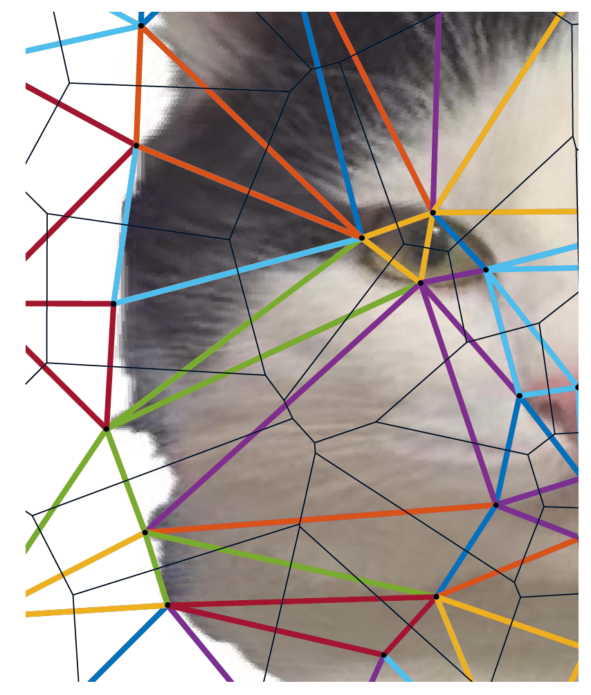
- Plot the triangles with different colors as shown here
- Plot the face fiducials to check if they match up with color coding the points
- View the warped images
- Plotting and indexing functions could be using [row, column] indexing which is different from [x,y] indexing. They are swapped such that x denotes column and y denoted row. Be sure to check documentation to see which function uses what.
- OpenCV documentation often has a lot of bugs with regard to indexing. Be sure to implement simple sanity checks.
9. Allowed and Disallowed functions
Allowed:
Any functions regarding reading, writing and displaying/plotting images in cv2, matplotlib
- Basic math utilities including convolution operations in
numpyandmath - Any functions for pretty plots
- Any function for blending
- Any function for Motion Filtering
- Any function for interpolation including
scipy.interpolated.interp2d - Functions for Delaunay Triangulation including
getTriangleList()function incv2.Subdiv2Dclass of OpenCV. However you are not allowed to use this for checking which triangle a point belongs to and to compute barycentric coordinates. - PRNet network and any helper functions for Phase2.
Disallowed:
- Any function that implements barycentic coordinate calculation.
- Any function that implements checking which triangle a point belongs to.
- Any function which implements in part of full the TPS.
10. Collaboration Policy
You are encouraged to discuss the ideas with your peers. However, the code should be your own, and should be the result of you exercising your own understanding of it. If you reference anyone else’s code in writing your project, you must properly cite it in your code (in comments) and your writeup. For the full honor code refer to the CMSC733 Spring 2019 website.
11. Acknowledgements
This fun project was inspired by a similar project in UPenn’s CIS581 (Computer Vision & Computational Photography).